The tough aspects of walking on sand
The locomotion of every moving system, alive or manufactured, is produced by the interaction between some movable components or appendages and the surrounding environment. This applies for every kind of surroundings: land, water or air. For water and air, Navier-Stokes equations allow predicting the interaction with the fluid with very high precision. In the case of land transmission, there are very simple equations for modelling the interaction with stiff soil, but there was nothing that could accurately predict the behaviour of a mobile advancing through “flowable ground”, such as grass, a layer of leaves, mud or sand.
Previous existing sand interaction models were extremely simple, as they were developed for big off-road vehicles, which indent the substrate very little. This simplicity caused prediction failures for small vehicles, including the Mars Rover, that have small wheels with extremely curved contact patches. Considering this limitation, Li et al 1 have studied the interaction of arbitrarily shaped rigid bodies with granular media. The complexity of this interaction is such that, at every time instant, each leg section is in a specific soil layer and has a specific speed, magnitude and direction (Figure 1); these are not constant, all of them will vary with time.

One alternative is to simulate the interaction of all the particles present in the media, with their particular morphologies, friction and cohesive environment. This means that every particle’s position and nonlinear interactions with the surrounding particles are calculated. There are accurate models that can do this, but the computational cost of these calculations when considering thousands of grains is so high that is absurd to consider it for real-time calculation of the forces of a robotic leg: it takes about 30 days to finish the simulation.
In order to create a valid and simple model for the prediction of the locomotive forces and displacements, the authors made the following hypothesis: the behaviour of the whole appendage is equal to the sum of the individual behaviours of infinitesimal elements along the whole interacting body. This had been proved very good approximation for basic geometries, and as it will be seen later, is pretty good also for the validation prototype.
The mechanical properties of granular media vary significantly with the grain size and the existence or absence of a cohesive fluid. For the study, dry sand was selected as reference case; the presence of a fluid complicates the modelling of the force-displacement relationship, and the high stiffness of the grains avoids the appearance of dissipative forces other than friction.
From a practical point of view, it is not very useful to use infinitesimal elements as the experimental validation of the model would be extremely complicated; thus, a finite plate with non-specified area A was tested in the experiment described in Figure 2A: the plate is introduced in the sand a depth z with an attack angle of β and a speed direction of γ. The vertical and longitudinal forces are then measured, and combining all the possible b and g angles, a contour plot is generated for each force (Figures 2C and 2D). With these maps it is possible to determine which variable values will generate the best lift and drag conditions for a discrete element. According to the authors, the resistive force profiles scaled to the depth were extremely consistent for the different media tested.

The next obvious step is to simulate and test different basic leg shapes, in this case C shape, flat and reversed C shape (Figure 3). The differences between the model (composed by 30 finite elements) and the tests are between 10% and 30% for different cases; anyhow, it is still much better than the previous model who took only into account the depth of the finite element, and not its speed direction, for the calculation of the drag and lift forces.
In this simulation it can be noticed that the C shaped leg is much more efficient generating lift and traction forces than the other two. If we go back to the contour plots in Figure 2, β and γ angles for the different elements of the leg are very close -or even coincident- with the maximum lift and drag forces that can be generated by a single plate. The circular shape of the leg makes a quasi-rolling element on the ground that allows an optimal placement of the different sections with their correspondent speed directions with respect to these contour maps. The flat leg, instead, has optimal lift only at the beginning of the contact, and optimal drag at the vertical position. The inverse C shape has no optimal contacts, as it “digs” in the sand instead of propelling itself: it has even negative lift forces when it tries to lift all the sand it dug.

Finally, the research team mounted the optimal legs in a prototype packed with sensors to see if their simulations of the full vehicle agreed with the experimental data. The vehicle consists of 6 C shaped legs, so that three of them are in contact with the soil at all times. The simulation of the multibody model, including their locomotion model, is compared to the experimental data in Figure 4. The longitudinal speed of the vehicle matches pretty consistently the one of the model. However, the most interesting graph is 4C, where different leg shapes are compared. There, it is easily noticed that all the C shaped legs have similar behaviour, achieving the same average speeds proportional to the leg’s angular speed, while reverse C shaped legs get slower speeds due to the digging effect; moreover, digger legs have a saturation on the speed of the vehicle after 3Hz: at greater angular speeds the longitudinal speed barely increases. The digging effect limits the propulsion of the vehicle, not only the lift.
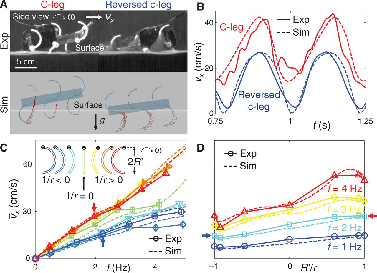
Does this mean that legs are better than wheels for sand locomotion? Not so fast. In the videos it can be seen that the behaviour of the vehicle is not smooth at all, even for C shaped legs. One of the good things of the wheels is that you always have the rolling centre at the same height from the ground. In this runner vehicle there are jumps and non-smooth behaviour everywhere, which can be acceptable in flat environments, but becomes very risky when a slope or a step appears. Yes, it is another good example of mechatronic biomimicry, but my educated guess is that it won’t go much further than some experimental prototypes; unless they manage to build a robot whose stability and reliability match the ones we have nowadays with good old wheels.
I encourage taking a look to the supplementary videos (edited by Francisco R. Villatoro), as they give a very good insight on the different parts of the paper.
References
- Li C., Zhang T. & Goldman D.I. (2013). A Terradynamics of Legged Locomotion on Granular Media, Science, 339 (6126) 1408-1412. DOI: 10.1126/science.1229163 ↩
1 comment
[…] against sand, then the needed pulling force is huge. But friction is tricky phenomena, and so are sand physics; so you can picture their combination. And now, a recent publication in Physical Review Letters has […]