Robot navigation on Mars
Robot navigation on Mars
Three main incorporations of physical robots are forecasted in our lives: transport, assistance and factory robots. Design and requisites of these different kinds are quite different, but one particularly is attracting researchers’ efforts: navigation. While transport robotics is located outdoors, the rest two are indoors. Outdoors machines can make use of a GPS (among other instruments) to navigate, but indoor robotics cannot and require extra aids to position and orientate. Among these, visual odometry system is the most used one for wheeled robots.
However, visual odometry implies assuming navigation errors and knowing the exact position of the robot turns to be a very hard task. There are two kinds of errors:
Systematic errors
-
Unequal wheel diameters
-
Average of both wheel diameters differs from nominal diameter
-
Misalignment of wheels
-
Uncertainty about the effective wheelbase (due to non-point wheel contact with the floor)
-
Limited encoder resolution
-
Limited encoder sampling rate
Non-systematic errors
-
Travel over uneven floors
-
Travel over unexpected objects on the floor
-
Wheel-slippage (slippery floors, over-acceleration, skidding in fast turns, etc.)
-
External forces (interaction with external bodies)
-
No-point wheel contact with the floor
Due to all these factors, probabilistic methods are one of the most powerful tools to calculate where the robot is located. But at the same time, if a robot starts from a perfectly known reference point, there will be an error propagation of its location due to the accumulation of uncertainties till it finds another known point. Obviously, if we added obstacles and walls, more complicated algorithms would be necessary which they would add extra errors to the navigation.
So how does the Martian Rover Curiosity get to know its position and orientation? In this case, it is equipped with an odometry system that computes an update to the six-degree-of-freedom (6-DOF) rover pose (x, y, z, roll, pitch, yaw). Certainly, attitude (roll, pitch, yaw) were measured using inertial measurement unit and three- axis angular rate sensors, and changes in position were estimated based on how much the wheels turned (wheel odometry). However, when the robot advances, a visual camera system is used in order to correct odometry calculus. Visual Odometry only corrects the rover’s position at the end of each step of less than 1 meter. The design goal for Curiosity was to maintain a position estimate that drifted no more than 10% during a 100-meter drive.
Considering that there is no GPS satellite deployed in Mars, Curiosity uses quite an original idea for the visual tracking, consisting on the Morse signs that wheels leave on the ground which help the camera system know the run distance and orientation, as can be seen in Figure 1.
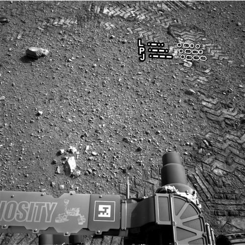
Thanks to this strategy, the robot was able to drive over terrains up to 31 degrees of tilt, and over textures comprised of a slippery sandy material, a hard-packed rocky material, and mixtures of both. Those cameras are based on Movarec’s (1980) visual tracking algorithms. In ground-based validations, two navigation systems dropped next results of errors in rocky and non-rocky terrains (see Figure 2).
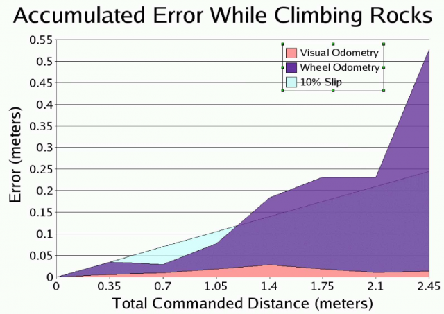
As can be seen in Figure 2, wheel odometry error is much bigger than visual odometry one.
References:
[1] Johann Borenstein: “Experimental results from internal odometry error correction with the OmniMate Mobile Robot”. IEEE Transactions on Robotics and Automation, Vol. 14(6), 963-969 (1998).
[2] Cheng, Y., Maimone, M., Matthies, L.H.: Visual odometry on the mars exploration rovers – a tool to ensure accurate driving and science imaging. IEEE Robotics & Automation, Vol. 14(2), 54-62 (2006).
[3] Fabian, J.; Clayton, G.M., “Error Analysis for Visual Odometry on Indoor, Wheeled Mobile Robots With 3-D Sensors,” Mechatronics, IEEE/ASME Transactions on , vol.19,(6), pp.1896,1906, Dec. 2014. doi: 10.1109/TMECH.2014.2302910
[4] Moravec, H. (1980). Obstacle Avoidance and Navigation in the Real World by a Seeing Robot Rover. Ph.D. thesis, Stanford University, Stanford, CA.
1 comment
[…] De hecho, la limitación de energía es uno de los factores más condicionantes del rover Curiosity, y por eso no puede montar un sensor LIDAR para escaneado de su entorno, al igual que hacen habitualmente los coches autónomos de […]