Finding collision-free tangential cutting directions when machining
Finding collision-free tangential cutting directions when machining

One thing is designing an object in a computer, and another, quite different, is producing it as a real 3D object. All other things being equal, in general the more curves the designed object has, the more difficult it is to produce. Mathematics can be very helpful in this task.
The geometric modeling of a curved object using contemporary CAD software as a set of NURBS surfaces is an industrial common practice . But the physical realization (or manufacturing) of curved objects is far more challenging. Given a free-form object, its realization as a tangible object has attracted a considerable research attention, for many years. The geometric challenges can be mostly found in multi-axis machining, where the tool can cut at its tip or on it side.
When the manufacturing process for a given object is itself designed, there are many factors that must be taken into consideration. From purely geometrical issues, like local and global accessibility, to the manufacturing technology that is going to be used, which includes the choice of tool’s shapes and sizes, not forgetting key physical parameters like the properties of the material of choice.
For example, for materials such as foam or polystyrene so-called hot-wire line-cutting is the most common machining methodology – to be precise this is subtractive manufacturing, as there is a controlled material removal. In hot-wire cutting the cutting tool is typically a thin straight conductive wire, stretched between two points on a rigid frame. During the manufacturing process, an electric current passes through the wire, heats it up, and the wire consequently cuts a ruled surface of the material, as it moves in space, forming the desired shape.
The development of hot-wire cutting machines started with 2-axis machines. Having the wire fixed vertically, the material block moves on a 2D platform, yielding two degrees of freedom. The state-of-the-art technology offers hot-wire machines with 5 degrees (or more) of freedom which can remove large amounts of material in a single cut, making it suitable for manufacturing of general 3D objects. Alternatively, the hot wire can be tensioned on a bracket, mounted on a robotic arm, to yield a multi-axis control.
Most recently, a robotic hot-blade prototype that consists of 18 degrees of freedom has been introduced. The extra degrees of freedom stem from the fact that the cutting curve is not a straight line, but a bent 3D curve. The tool-path planning algorithm uses the bending energy of the wire to adapt its shape dynamically to the surface during the cutting process. While having that many of degrees of freedom is an advantage from the point of view of approximation quality, curved wire is a fragile tool and a straight wire dominates the industry.
Now, consider hot-wire cutting with a straight wire in a multi-axis cutting context. Given a set of cut-paths on a freeform geometry as the input, it is necessary to develop an algorithm for finding collision-free tangential cutting directions for the manufacturing process to be, firstly, feasible, and, secondly, efficient. A team of researchers that includes Michael Bartoň (BCAM), has developed excatly that algorithm 1 focusing solely on the geometric aspects of line-cutting, most notably the accessibility questions.
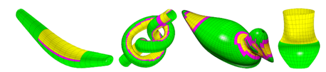
The researchers study the accessibility of a free-form surface for a 5-axis milling machine. Motion of the tool axis is navigated by exploring a three dimensional search space. The first parameter is the parameter value of the input contact curve over the free-form surface, and the other two are a pair of angles determining locally the orientation of the tool’s axis (inclination and tilt angles). The search space is subdivided until a conservative estimate of admissible positions of the milling axis is found. This approach guarantees globally accessible and gouging-free configurations of the milling tool.
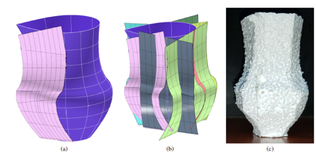
The researchers apply the algorithm to some examples, as those depicted in figure 1. In the case of the vase, they use a rough covering of the input vase surface with isoparametric curves. Along with a tangent line-accessibility analysis and the motion planning described by the algorithm, they create the line-accessible cut-paths that is shown in Figure 2. This cutting was used to drive a robot yielding the final cut part, from Styrofoam, shown in Figure 2 (c). The actual cutting is shown in the following video:
Future algorithms that could combine both the ruled surface approximation and this new lineaccessibility analysis will be able to generate high-quality, collision-free cutting paths.
Author: César Tomé López is a science writer and the editor of Mapping Ignorance.
References
- Boris van Sosin, Michael Bartoň, Gershon Elber (2019) Accessibility for Line-Cutting in Freeform Surfaces Computer-Aid Design doi: 10.1016/j.cad.2019.05.014 ↩
4 comments
As we have seen in many movies and TV shows on how CGI effect is created out of object which is generally supported by some kind automated robotic system which make its movie act like real life things in movie. In conclusion, robotic automation companies are making it to media industry as well.
[…] Askatasun 5 gradu dituen robotizatutako mozketa tresna bati jarraibideak ematea edozein modutan objektu tridimentsionalak sor ditzan ez da hutsala. Jarraibide horien garapenak matematika aplikatuak behar dituenez, BCAM: Finding collision-free tangential cutting directions when machining […]
[…] Mapping Ignorance: Finding collision-free tangential cutting directions when machining […]
[…] Mapping Ignorance: Finding collision-free tangential cutting directions when machining […]