The comfort of modern trains
The comfort of modern trains
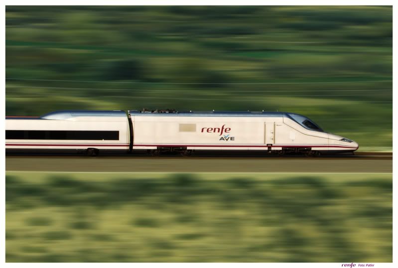
High speed trains are the best example of vehicles that, although operating at somehow extreme conditions, are very comfortable. And by comfort I mean that the vibration level that passengers feel is relatively low. The components that allow this level of comfort are the pneumatic springs, torus-shaped rubber elements filled with pressured air. Their behaviour is similar to the coil springs, as for a given compression force they get a specific deformation. You can think of it as a balloon pressed against the floor: the harder you press the higher deformation you get.
Nowadays almost every passenger vehicle mounts air springs in their secondary suspension, typically composed by a compression chamber, an auxiliary rubber spring, an auxiliary chamber and a connection pipe (Figure 1). The auxiliary rubber spring is meant to support the carbody in case of failure of the pneumatic system. There are several advantages of pneumatic suspension systems compared to coil springs:
- The height of the suspension can be controlled by feeding in or out more air. This allows a constant height of the carbody, not dependant on the occupation of the train. This height regulation is also used in urban buses to tilt in order to decrease the height of the step.
- There is some damping introduced by the losses of the air flow through the connection pipe. In most cases this avoids the use of a vertical damper, reducing costs and complexity of the system.
- Its force-displacement characteristic is proportional to the air pressure, and thus the natural frequency of the vertical mode is independent of the sprung mass. This is very good for vehicle designers as the optimized suspension parameters are constant for every load condition.
- It filters high-frequency oscillations, reducing the vibrations transmitted from the bogie to the carbody.
- The load of each spring can be easily and accurately measured, allowing the modification of acceleration and braking for a better performance in multiple unit vehicles.
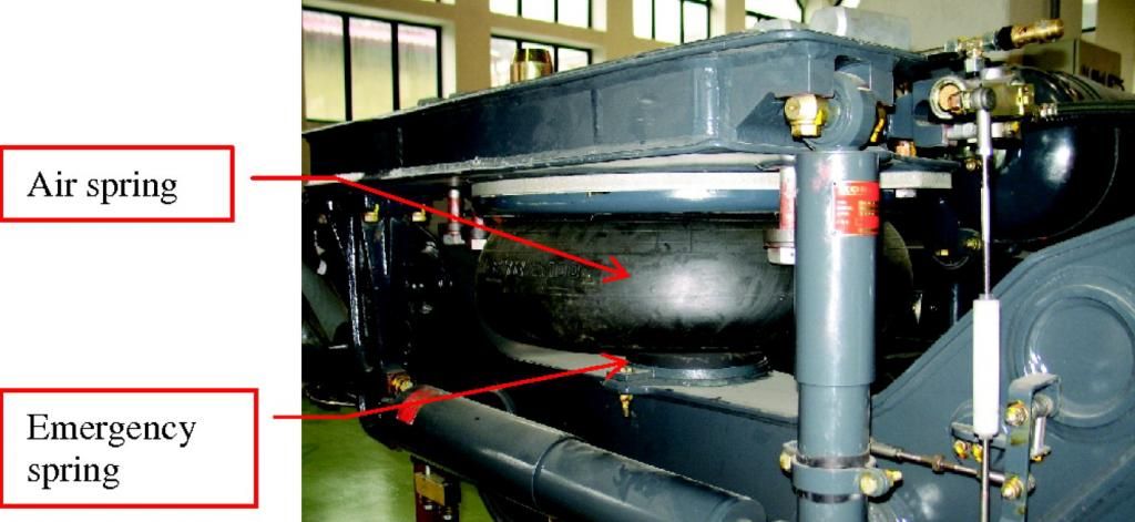

Air springs have a long history of usage, the first ones being installed in the 1960s for high standing vehicles. The modern design is actually very successful and widespread, with very little modifications from the original design, because of the high comfort level it provides. Several mathematical models have been developed which represent the behaviour of these components, with increasing complexity. However, Evans and Berg 1 claimed that, in order to improve railway simulation models, air spring modelling must be seriously tackled. Alonso et al. 2 took the bait and performed a deep modelling analysis and experimental validation on air springs. And the most interesting bit of their work is that they managed to introduce a small tweak in the system that will allow vehicle designers to improve the comfort of their vehicles even more. But we will get to that eventually.
Air spring
The particular behaviour of air suspension elements is generated by the connecting pipe. If the speed (frequency) of the excitation is low, the air can flow between the two chambers easily and the stiffness is that of the two volumes. But if the speed is high, the viscosity of the air makes it more difficult to flow between the two chambers, and thus the air gets stuck in the pipe and the stiffness of the element is increased. The Frequency Response Function (FRF) represents the dynamic stiffness of the air spring depending on the frequency of the input excitation. Figure 2 shows its behaviour for the studied air spring.
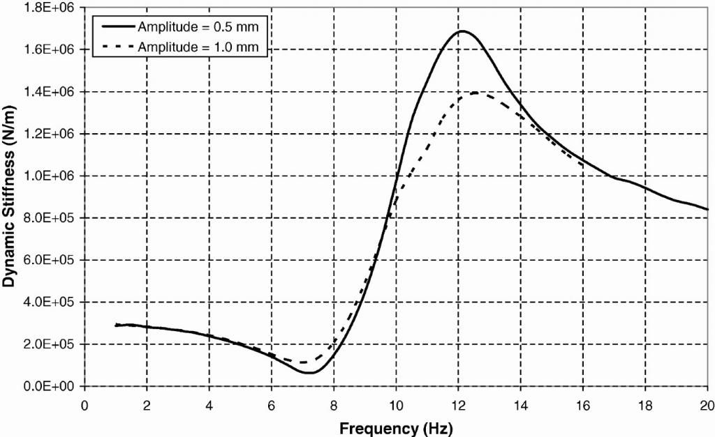
There are two noticeable aspects: i) there is a resonance peak at c.a. 12Hz and ii) the maximum value of this resonance peak is not constant, but depends on the amplitude of the input displacement.
This last behaviour appears because, for higher amplitude in the displacement, higher air speeds will be achieved in the pipe with higher energy dissipation. However, the pressure loss in the pipe is not proportional to the speed, but follows a quadratic law, modifying the damping value for different air speeds. The dynamic behaviour depends on the damping, so it directly affects the FRF.
This is a drawback for vehicle designers, as they cannot choose the characteristics of the air springs that maximize passenger comfort; it will eventually depend on the excitation level, this is, the vertical irregularities present on the track, which will be different for each track section. According to the authors, this influence is proportional to the amplitude of the excitation: for double amplitude the Normalised Comfort Parameter is also doubled.
Improving Comfort
The premise for the solution of the problem is quite simple: we need a pipe that generates a proportional damping. The solution is quite creative, though: we will make the cross section area of the pipe variable, so the overall loss is not dependent on the displaced air. Figure 3 shows a scheme of the proposed device that will allow the section to be variable.
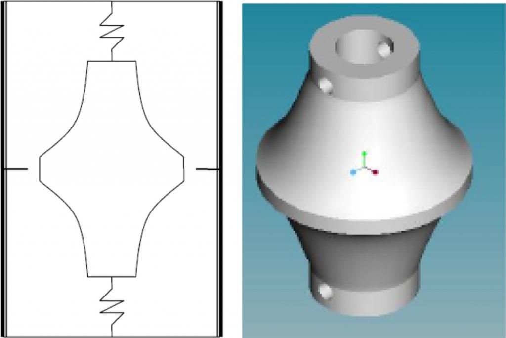
When the device is installed in the connection pipe it will act as a section orifice. As it is held by coil springs, its cross section will increase when a pressure difference appears between the two sides of the mechanism, and will be constantly increasing with the value of the excitations. With a bigger section the losses will be lower, and thus the quadratic effect of the speed is compensated in order to keep the damping constant. Figure 4 depicts the laboratory results of an air spring that includes the prototype.
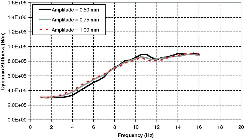
The results show that the dynamic stiffness of the air spring is completely independent of the amplitude of the excitation. In vehicles that implement this novel solution, passenger comfort will be optimized for every railway that these vehicles are running, regardless of the vertical track irregularities. Even successful 50 year old designs can be improved when all their characteristics are studied in detail.
References
- J. Evans and M. Berg, (2009) Challenges in simulation of rail vehicle dynamics, Vehicle System Dynamics: International Journal of Vehicle Mechanics and Mobility, 47(8), pp. 1023–1048 ↩
- A. Alonso , J. G. Giménez , J. Nieto & J. Vinolas (2010): Air suspension characterisation and effectiveness of a variable area orifice, Vehicle System Dynamics: International Journal of Vehicle Mechanics and Mobility, 48:S1, pp. 271-286 http://dx.doi.org/10.1080/00423111003731258 ↩
1 comment
It is not easy to find a Rail Vehicle Engineering paper as complete as this one about a specific topic. If you found it interesting I recommend you to read the whole paper, it will be understandable for anyone with basic engineering knowledge.