The limits of high speed rail
The limits of high speed rail
Author: Iván Rivera works as an engineer in innovation projects for railroads
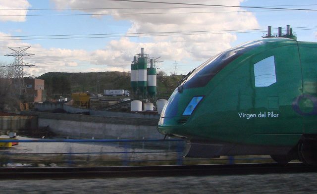
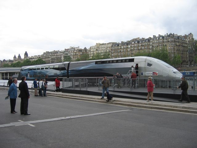
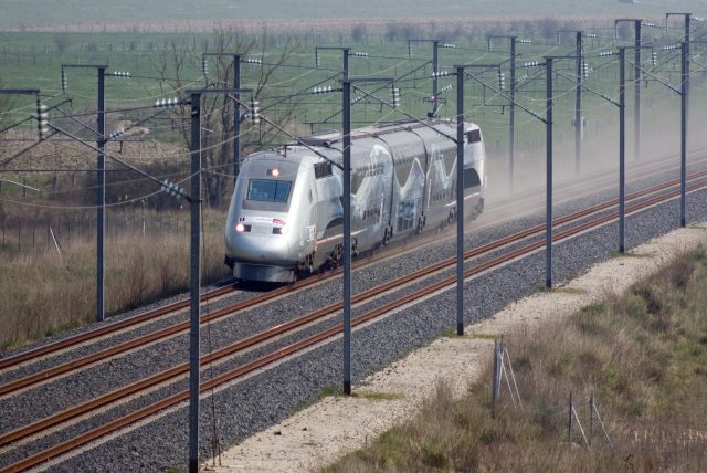
Twelve years have passed since the world record for rail speed was set. “Operation V150”, which got its name from the target speed for its testbed trainset, 150 metres per second (540 km/h), occupied from January 2007 to April of the same year a team formed by the french railway operator SNCF, the infrastructure manager Réseau Ferré de France and Alstom, the rolling stock manufacturer. On April 3, 40 seconds past 1:13 p.m., the TGV V150 built for the occasion by the latter company reached 574,8 km/h at the 194 km point on the TGV-Est line between Prény and Champagne-Ardennes stations, near the town of Éclaires — in what was perhaps an involuntary poetic turn for the engineers in charge of the program, as éclaires translates in English as “(you) illuminate”.
With a total expenditure of 30 million euros, Operation V150 was not just a publicity stunt to cement the national prestige of an industry in the face of tough German and, increasingly, Chinese competition. During multiple test runs which allowed the trainset to unofficially break the previous 1990 record (515.3 km/h) on several occasions, the project engineers monitored in detail the behaviour of the vehicle, the track and the overhead contact line to determine in each case their operational limits.
What conclusions can be drawn from this experiment for the railroad, more than a decade later? Why has the maximum speed of trains seemed to stagnate at 350 kilometers per hour for so long? To understand this, let us take a look at the railway system, paying particular attention to the factors that may limit its performance.
Wheel-rail contact
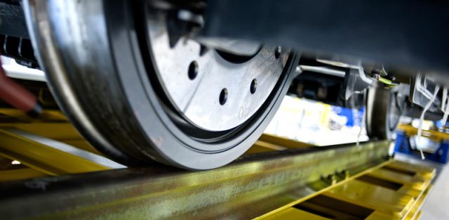
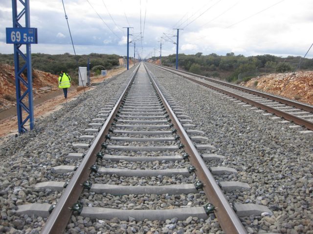
The railway is guided land transport mode, which means that it can only move along a structure — the track — formed by rails parallel to each other, held in place by fastenings to sleepers, usually made of concrete. The track is not anchored to its platform: it just rests on it. Its stability is ensured by its own weight. The wheels of the train, made of steel like the rails, have a slightly conical profile topped by a flange on the inner side that ensures that the axles remain centred on the track without derailments [Casanueva, 2014]. The profile of the wheels guarantees centering during most of the journeys by leaning on the head of the rail, while the flanges hold the train in place in case of excessive lateral displacements.
As long as the track does not branch at a turnout, its geometric structure is formed by a sequence of straight lines and arcs of circumference joined together by clothoids to avoid discontinuities in curvature radii. Radii are infinite for straight lines and finite in full curve; clothoids allow a smooth transition between these two conditions and, therefore, eliminate possible jumps in radial accelerations experienced by the trains along their journey. In order to further limit this acceleration and therefore tolerate smaller curvature radii, tracks in curves are designed with a cant: the vehicle running plane is inclined towards the inner side of the curve at an angle that depends on the expected speed of the trains and their weight per axle.
Undoubtedly, the wheel-rail contact is one of humanity’s great inventions when it comes to reducing the energy needed to transport large quantities of passengers and cargo. The contact surface per wheel on the rail head is barely 250 mm², guaranteeing minimum frictional forces — the rolling resistance coefficient for steel on steel contact is, at its worst, 30 times lower than that of rubber on asphalt.
However, in Physics it is never possible to achieve anything without sacrificing something else in return. The ability to move hundreds of tons with moderate tractive forces is only obtained in exchange for losing the ability to brake in short distances or to overcome steep slopes. It is intuitive if one considers how a car behaves on asphalt as opposed to its reactions over icy ground. Moreover, if the width of the wheels is reduced and they are manufactured in a material with a lower friction coefficient (so as to say, “smoother”), it should not be surprising that a light passenger train requires a few hundred metres to stop, while a heavy merchant would need one or two kilometres of track.
Aerodynamics
Long ago, the shape of trains’ end faces was designed with no regard to aerodynamics. The speed they reached was not enough for engineers to worry about resistance of the air to the advance of such a heavy vehicle. However, the advent of more capable power plants brought with it a concern to find ways to penetrate the air more easily. The explanation for this is to be found in the relatively simple equation of aerodynamic drag force, which states that air drag is directly proportional to the square of speed [1].
The struggle to minimise the aerodynamic drag coefficient, initially empirical and carried out in wind tunnels, and later numerical and executed by means of simulations carried out on supercomputers, presents its own limits. A fairing with a good drag coefficient can be improved by means of specific skirts for pantographs, retractable coupling systems or by reducing the separation between carriages. However, it easily becomes self-evident that compromises are needed with respect to the maintainability of the system or its own durability. In particular, the separation between carriages must be sufficient to accommodate their flexible connections in curves. How a train made up of fundamentally rigid elements easily takes curves is a matter for another article.
Pantograph-catenary contact
The wheel-rail interface is the most obvious one for laypeople who have not paid too much attention to the physical layout of the railway system. It is also the only mechanical interface found in diesel-powered trains. However, diesel power plants have intrinsic limitations which do not affect electric trains. In short, the performance of internal combustion engines is limited by Carnot’s second theorem and the (fixed) combustion temperature of the diesel-air mixture. No diesel engine has therefore performances higher than 48%, so being able to yield more power — and ultimately attain higher speeds — is only a matter of increasing the number of cylinders. This, in turn, increases fuel consumption, which must also be transported in specific tanks.
This particular set of engineering compromises meant that the world speed record for a diesel engine powered train has been set at 238 km/h since 1987, although not without some controversy: the Talgo XXI prototype (currently at the service of the Spanish infrastructure manager Adif as a laboratory train) reached 256.38 km/h between Olmedo and Medina del Campo in 2002. Record registration was, however, not officially accepted due to the lack of an independent verification.
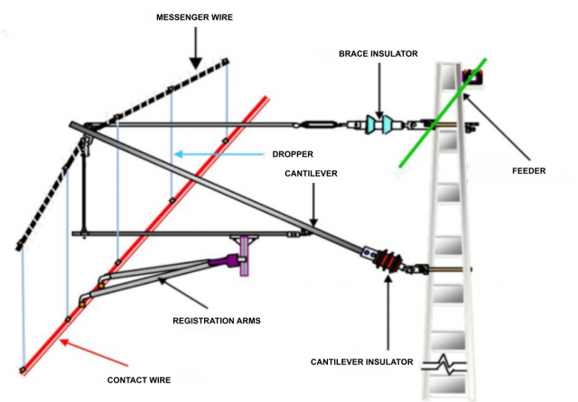
Electric trains have a second mechanical interface. Since it does not transport its own source of energy, an electric train takes advantage of the electric current it draws from a mobile contact with a conductive structure located over the tracks — we shall not concern ourselves with third rail power supply, since it cannot be used at high speeds due to safety and friction requirements. This mobile contact is made by means of a pantograph: an articulated arm that holds one or more carbon (or copper) contact strips pressing against the overhead contact wire. This wire is made from a highly pure copper-silver alloy with very low electrical resistance and friction coefficient, and high resistance to wear.
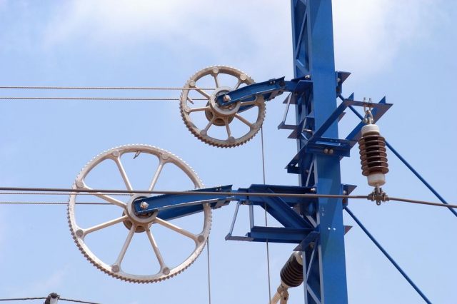
The contact wire has to comply with two sets of disparate physical requirements. On the electrical side, the wire has to withstand the maximum current drawn from train power plants. To keep this current manageable — and therefore keep Joule effect losses and ultimately wire temperature below operational limits, and given that the wire alloy conductivity is already optimized, nominal voltage or wire section (or both) should be increased. On the mechanical side, the wire has to be kept taut so as to maintain a shape as horizontal as possible — this will improve the contact quality, and therefore power transmission and system durability. Naturally, the weight of the wire itself causes it to sag, so it should be as light per unit length as possible. Wire deflection is reduced by increasing mechanical tension, which is kept constant thanks to a variety of tensioning mechanisms that maintain its desired value during daily and seasonal temperature changes. Increasing tensile force cannot be done without a bigger wire section and more robust (read: expensive) equipment overall.
.
The forces involved in pantograph-catenary contact are negligible when calculating a train’s tractive effort, but must be taken into account when determining the durability of the overhead contact line itself. Being a light structure kept taut by forces several tens of kilonewtons’ worth, and designed to withstand kiloamperes of electrical current, the system conflicting engineering compromises keep it on a hard-earned equilibrium where damages can be both mechanically and electrically induced. These damages can be nominal, causing expected wear on the structure, or catastrophic, causing de-wiring and pantograph destruction.
The V150 Operation
The tasks of Operation V150 were carried out in two different areas. On one side, a laboratory trainset capable of reaching speeds over 150 m/s (540 km/h) was built — hence the name of the project, TGV V150 (from French “Train à Grande Vitesse”, high speed train). On the other, a specially selected 94-kilometre section of the TGV Est line was fitted out. Featuring a slight uniform downward slope and sufficiently large curve radii, it could easily accommodate all the tests to be carried out. Project circulations began in January 2007 and ended in April, with gradually increasing speeds. A total of almost 1,000 kilometres were recorded over 500 km/h.
The V150 trainset was formed by an unusual composition of three coaches located between two driving heads: two double-deck units and a central cafeteria car, specially built for the occasion and fitted out as a laboratory. In addition, it had a series of modifications specially designed for the record attempt.
Propulsion was provided by both locomotives in a push-pull configuration and by two articulated AGV motor bogies [2] mounted on the ends of the cafeteria coach. The asynchronous motors of the locomotives had been uprated by 56% above the usual value in their class, up to 1950 kW. The permanent magnet synchronous motors at the AGV bogies were also adjusted to 1000 kW (39% above their rated power). In this way, the total power of the full trainset could reach 19.6 MW.
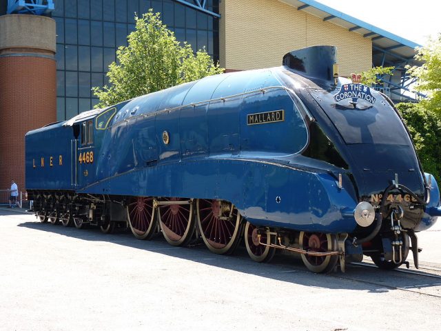
An old engineering trick used in steam locomotives was called upon: increasing wheel diameter. This allows ti improve speed at the expense of torque — which fundamentally affects starting, not much of a problem in a relatively light train composition. Wheels of 1092 mm were mounted as opposed to the usual ones of 920 mm. The subsequent slight increase in the height of the trainset was compensated for, in order to improve its aerodynamic performance, with larger skirts around its full contour.
In addition to this, the modifications designed to address the flow of air at speeds above 150 m/s were extensive. The two-piece retractable fairing, which protects the endcarriage Scharfenberg automatic coupling system, was replaced with a single continuous piece. A special windscreen was flush-mounted with the bodywork, and the windscreen wipers were removed. The entire underside of the train was paneled to reduce aerodynamic drag and protect components exposed to damage from ballast flight, due to the turbulence caused by high-speed traffic.
In addition, the DC pantographs that allow the operation of this locomotive model over DC-fed lines were removed, and their recesses covered by flush-mounted panels. Separations between carriages were protected with flexible surface joints. Specific skirts were even designed for the bogies, but they were not used during the record event.
Infrastructure modifications
The railway is a transport system in which vehicles and their corresponding infrastructure are strongly coupled. For this reason, it was foreseeable that the track and catenary of the V150 programme would also undergo a series of adjustments and modifications aimed at ensuring a successful end result.
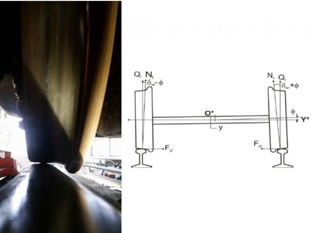
The agreement curves between straight lines and circumference arcs of the rail path were thoroughly checked and adjusted to ensure completely smooth transitions and no normal acceleration discontinuities. The cant of all curves, as well as their corresponding cant transitions, were increased by up to 130 mm to prevent the train from running under the condition known as cant deficiency, which causes the flanges of the wheels on the outer side of the curves to press against the head of the rail, causing premature wear of both rail and wheels.
A specially profiled ballast was used to reduce the impact of the above-mentioned ballast flight effect. Finally, as far as the track is concerned, all the points in the test track (fitted with swingnose crossings) were manually locked into the straight track position, thus minimising any possible physical discontinuity in the rails.
As far as the overhead contact line is concerned, both electrical and mechanical changes were made. The groups of substations and autotransformers designed to maintain a constant no-load voltage of 25 kV of alternating current along the entire route were altered to provide maximum voltages of 31.7 kV. Specially designed capacitor banks were added to support the autotransformers and absorb the extra reactive power generated by the higher inductive loads of the V150 trainset motors.
The key factor for very high speed circulation, however, is the mechanical response of the catenary. Its behavior is easy to understand picturing a finger pressing a guitar string. The finger represents the pantograph of a train. By moving longitudinally through the catenary applying a vertical force to ensure the continuity of the electrical contact, the pantograph creates a wave that moves in both directions along each span of automatic compensation of the mechanical tension of the catenary.
The frequency of the generated wave increases with mechanical stress — and for that reason the tighter strings of a guitar sound sharper. But if the finger is pushed along the string instead of just plucking it, the wave ceases to be static and moves at a speed proportional to the mechanical tension and inversely proportional to the mass per unit length of the string material [3].
This idealized scenario is altered by the existence of fixed masses in the overhead contact line, which are indispensable for its mechanical support. Droppers and registration arms, which allow the shape of the contact wire to be maintained by anchoring it to the messenger wire and to the masts respectively, induce reflected waves that alter the behaviour of the entire assembly. At high speeds, the dynamic interaction between the pantograph and the overhead contact line is further complicated by the Doppler effect, which shortens the waves in the direction of travel — while lengthening them in the opposite direction.
Since the contact wire used during the record runs was the same one used in standard installations, the only parameter that could be altered was its mechanical tension: from the nominal 25 kN it was increased to 40 kN — the tension equivalent to hanging a mass of approximately four tons from the wire. The estimated speed for the resulting travelling wave disturbance would be 610 km/h, leaving an ample enough safety margin with respect to the speed finally reached by the train.
The record run
At exactly one p.m. on April 3, Daniel Beylot, head of Operation V150, issues the starting order. Eric Pieczak, the engineer appointed to drive the train during the record attempt, acknowledges the command. Georges Pinquié, traction inspector, and Claude Maro, director of the corresponding department, are also in the cabin. On board the train, and showing the absolute confidence of the engineers in the safety of the test, are a total of 105 people, including the president of SNCF, Anne-Marie Idrac, its General Director, Guillaume Pépy, the president of RFF, Hubert du Mesnil and the European Commissioner for Transport, Jacques Barrot, along with a large number of guests and journalists.
Three large-format television cameras and ten additional minicameras mounted at different points on the train broadcast live footage of the run to the national news. Next to the track, seven additional cameras would capture images of the train — one at the place of departure and one at the place of arrival, with five more arranged in the area where the speed record was expected to be achieved. An additional camera aboard an Aérospatiale Corvette jet would track the speeding train along the entire route. The surroundings of the railway, and in particular all the overpasses and the Meuse station, halfway along the route, are crowded with spectators.
The train leaves Prény and quickly reaches the neutral zone of the catenary that separates the conventional 25 kV high-speed power supply from the one fed at 31 kV from the prepped-up Trois Domaines traction substation. Following the usual protocol for changing the power supply, Pieczak lowers the pantograph when entering the neutral zone, and raises it again at the exit. It is now 1:05 p.m.
On reaching the 500 km/h mark, the camera controlling the pantograph condition already shows a continuous electric arc. Arcs, caused by irregularities of the physical contact between pantograph and contact wire, are one of the fundamental factors that decrease the durability of both elements. At 1:10 p.m. the Meuse station passes in front of the elated passengers in the blink of an eye. The train lifts a cloud of dust in its wake, vacuumed from the ballast under the track. The speed is now 535 km/h.
The official record attempt target is 540 km/h, which is surpassed amid a round of applause. Finally, the train surpasses 574 km/h before starting its deceleration. At one thirty p.m. it is already coming to a halt on the platform at Champagne-Ardenne station. The advertising tour de force has been achieved.
Is sky the limit?
Alstom engineers seemed confident that the test did not subject their train to any extreme conditions. They believed it was possible to exceed 600 km/h, even though reaching that speed would have put the pantograph dangerously close to that of the travelling wave disturbance of the overhead contact line. Should that speed be exceeded, the train would then overtake its own generated wave causing an effect similar to that of an airplane surpassing the speed of sound. The contact regime between the pantograph and the catenary would undergo an abrupt change, which could even lead to de-wiring and the destruction of the whole assembly.
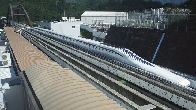
There was also a purported “diplomatic” limit: five years earlier, a Japanese maglev had set a speed record at 581 km/h. The French managers considered it pointless as well as prudent to force the experiment to exceed that speed, as they could have entered a kind of “international race” that they did not have much chance of winning. Time would prove them right: in 2015, another L0 series maglev reached 603 km/h on the Yamanashi test line. All communication related to Operation V150 stressed that the results obtained were only relevant for wheel-rail contact technology and overhead contact wire power supply.
It seems clear that a practical limit with current rail technology would be hit before reaching 600 km/h. Solving the technical problems of pantograph-catenary contact at such speeds involves increasing the mechanical tension of the wire, which would compromise its strength and force the use of larger wire cross-sections. This, in turn, would have cascading effects throughout the system, increasing the fixed mass weights and further complicating contact integrity.
Coming back down to earth
Today’s technology seems to indicate the 600 km/h mark as a top speed limit for the railway. However, the usual operating conditions, in which rolling stock compositions routinely cover millions of kilometres, are necessarily more conservative than those of a project such as Operation V150. From the point of view of safety as well as energy consumption and the need for controlled maintenance costs, it is necessary to come back to earth and re-examine the situation of commercially available technology to understand why top speed trends seem to have plateaued around 350 km/h, as well as what possibilities remain relevant in the long term.
The operating conditions of a high-speed railway line quickly reveal themselves as limiting factors. Operation V150 revealed that aerodynamic phenomena are dominant in train behaviour above 500 km/h, but for obvious reasons the tests did not include some of the most significant effects of this type on commercial operation: interaction with infrastructure in tunnels, affectation due to cross traffic and the effect of crosswinds in vulnerable areas such as viaducts. For this reason alone it is reasonable to assume that no current train could commercially reach 500 km/h without extensive modifications. In addition, the most advanced signalling in use on high-speed lines (ETCS/ERTMS) reaches its limit precisely at this speed level.
This assumption fits perfectly with the latest speed records recorded by commercial trains. The Chinese CRH380BL, a 16-car and widened gauge variant of the Siemens Velaro, reached 487.3 km/h in January 2011 on a section of the Beijing-Shanghai line. Back in Europe, and without any special preparation, Renfe reached in July 2006 the 403.7 km/h mark between Guadalajara and Calatayud with an S-103 unit (another Siemens Velaro incarnation) — setting for a short time the world speed record for commercial trains.
Practical boundaries
In Feng, Sun, Liu, & Li (2014) a model is proposed for estimating the energy consumption of a high-speed train as a function of the top speed on a given route. A numerical example for the Shanghai-Hangzhou line gives the following result:
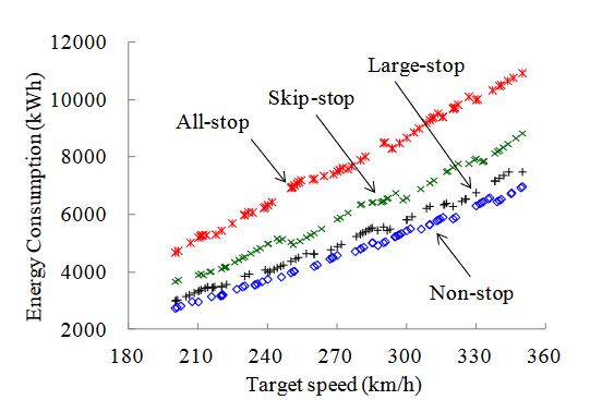
The railway line in the sample case is 169 km long and has nine possible stops, including the initial and final stations. These are used to establish four operation strategies: local service, skip-stop service, express service with a single stop and non-stop service. It is interesting to observe how a non-stop train with a target top speed of 300 km/h achieves a total energy consumption which matches that of another train with three intermediate stops (skip-stop service) and a top speed of 250 km/h. Conversely, if we set the top speed at 300 km/h, the train performing skip-stop service requires almost 30% more energy than non-stop traffic.
This result helps in realizing that the operational mode is critical in determining the viability of a high-speed system, since it is the number of intermediate stops and not so much the target top speed, in the ranges studied, which determines the final energy usage. At the same time, it is possible to make a reasonable extrapolation above the range of speeds covered by the model to assess how setting a 400 km/h top speed for a non-stop service would yield a similar energy consumption to a skip-stop strategy with a 350 km/h top speed.
The issue to be addressed is thus clarified. The commercial operation of high-speed rail must seek both economic profitability and control of the environmental footprint. The latter is theoretically possible thanks to the flexibility offered by the energy source used, and depends on the particular power generation mix of the region where the railway is located, which is outside the scope of this article. Cost-effectiveness, on the other hand, depends on whether we are able to compensate for the energy consumption with the train’s transport productivity, measured in passenger-kilometres [4].
It is possible, then, that simply by increasing the gross transport capacity of a train (and keeping, of course, its occupancy high), an increase in top speed can be compensated, both from the point of view of energy consumption and maintenance expenditure — more complex to model — with higher productivity. The railway strategies to achieve this without increasing the number of running trains are well known: from slightly increasing gauges to allow cars with a seating arrangement per row of 3+2 (as in the case of China railways), through a reduction in the space available per passenger for the same purpose (as will be demonstrated by the latest Talgo model, AVRIL), using double-decker cars (Alstom is the undisputed leader in this category with the TGV Duplex used in French high speed network), dispensing with first class and cafeteria cars (as in SNCF’s OUIGO service) or, quite obviously, to operate trains in double composition — two trains joined, an option that allows doubling the number of passengers without consuming double the energy.
The high-speed train of the future can reach 400 kilometres per hour if it restricts its stops and moves large numbers of people at the same time. Now it is our turn, not only as engineers, but also as managers and policy-makers, to decide whether this is desirable, what the alternatives are and what is the transport system with which we want to face the challenges of the future.
Notes
1. The aerodynamic drag force can be expressed in this way: D = 1/2 Cd ρ A V² , where D is the force opposing the advance, Cd is the coefficient of aerodynamic drag (determined by the shape of the moving object), ρ is the density of the air (at sea level, under normal conditions, it is around 1.2 kg/m3), A is the cross-sectional area of the train (in the case of the railway it is practically constant for all vehicles and corresponds to the area of the kinematic gauge, i.e. the smallest gap through which a train passes without colliding with elements of the infrastructure), and V is the speed in the direction of travel.
2. A bogie is a rigid assembly usually made up of two axles — and therefore four wheels — that contains the fundamental elements to ensure the inscription in curves of cars, braking, suspension and, in some cases, also train propulsion. The bogies are mounted at the ends of the cars or, as in the case of articulated compositions, between two cars. Not all train types feature bogies: the most characteristic example of a composition with simple axles is that of the Spanish Talgo system.
3. The propagation velocity of the travelling wave induced by the pantograph can be expressed as Cp = √(T/m), where T is the tension in Newton and m, the contact wire unit length mass in kg/m.
4. The passenger-kilometre (and not “passengers divided by kilometre”), or p-km, is a unit of measurement of transport capacity which allows individual trains or complete lines with several trains to be compared with each other without the need to take into account differences in gross capacity or distances travelled.
REFERENCES
Anyakwo, A., Pislaru, C., Ball, A., & Gu, F. (2011). Modeling the dynamic behaviour of the wheel rail interface using a novel 3D wheel-rail contact model. 5th IET Conference on Railway Condition Monitoring and Non-Destructive Testing (RCM 2011). doi:10.1049/cp.2011.0616
Casanueva, C. (29/10/2014). Los trenes no se van por la tangente. Visited on August 18th, 2019, at https://ccasanueva.wordpress.com/2014/10/26/los-trenes-no-se-van-por-la-tangente/.
DVV Media International Ltd. (01/05/2007). V150: Power-packed train proves AGV technology in record sprint. Visited on August 18th, 2019, at https://www.railwaygazette.com/news/single-view/view/v150-power-packed-train-proves-agv-technology-in-record-sprint.html.
DVV Media International Ltd. (01/05/2007). V150: 574·8 km/h eclipses the 1990 world record. Visited on August 18th, 2019, at https://www.railwaygazette.com/news/single-view/view/v150-5748-kmh-eclipses-the-1990-world-record.html.
Feng, X., Sun, Q., Liu, L., & Li, M. (2014). Assessing Energy Consumption of High-speed Trains based on Mechanical Energy. Procedia – Social and Behavioral Sciences, 138, 783-790. doi:10.1016/j.sbspro.2014.07.260.
Liu, Z. (2017). Measures to Enhance the Dynamic Performance of Railway Catenaries. Stockholm: KTH Royal Institute of Technology.
Researching the train of the future. Cologne: Deutsches Zentrum für Luft- und Raumfahrt, Institute of Vehicle Concepts. Visited on August 18th, 2019, at https://www.dlr.de/dlr/en/desktopdefault.aspx/tabid-10467/740_read-916/#/gallery/2043.
Wu, J. (2018). Dynamic Interaction Between Pantograph and Contact Line. In Chapter 4: Pantograph and contact line system (pp. 130-131). London: Academic Press.
24 comments
“density of the air (at sea level, under normal conditions, it is around 1.2 kg/m²)“
1.2 kg/m² Must be 1.2 kg/m3
Cubic meter not square meter
Thanks for spotting the typo!
[…] The limits of high-speed rail 6 by bookofjoe | 0 comments on Hacker News. […]
[…] The limits of high-speed rail 6 by bookofjoe | 0 comments on Hacker News. […]
[…] Source link […]
[…] The limits of high-speed rail 6 by bookofjoe | 0 comments on Hacker News. […]
[…] The limits of high-speed rail 7 by bookofjoe | 0 comments on Hacker News. […]
[…] The limits of high-speed rail 7 by bookofjoe | 0 comments on Hacker News. […]
[…] The limits of high-speed rail 13 by bookofjoe | 0 comments on Hacker News. […]
[…] The limits of high-speed rail 13 by bookofjoe | 0 comments on Hacker News. […]
[…] The limits of high-speed rail 21 by bookofjoe | 1 comments on Hacker News. […]
[…] The limits of high-speed rail 31 by bookofjoe | 4 comments on Hacker News. […]
[…] The limits of high-speed rail 49 by bookofjoe | 9 comments on Hacker News. […]
[…] The limits of high-speed rail 63 by bookofjoe | 13 comments on Hacker News. […]
[…] https://mappingignorance.org/2020/01/22/the-limits-of-high-speed-rail/ […]
More importantly, “éclaires” translate to “lightnings”. Even more of a poetic turn 😉
éclairs, not éclaires, translates into lightnings. éclaires comes from the verb éclairer and means “you illuminate” as correctly stated in the article. Still quite poetic. And thanks to the author, great article.
I noticed a lack of mention on how with conventional,but underdeveloped technology each of the issues can be further mitigated or overcome.
Power delivery friction and tension issues can be overcome by using on engine car batteries, which charge when the train is near the station.
Acceleration can be overcome with liniar induction motors as the car is leaving the station to offload some of that burden onto an external source.
Similarly an external dedicated braking surface can speed braking by simply not using the wheels as the braking surface.
For speed of the rail contact stability there are greater issues, for small increases, improving the alloy and polishing the rail surface can work with the above methods. The use of a curved conical surface and curved top rail can reduce contact area.
Anything further would require something more exotic like groung effect and/or maglev. This would not have nearly the cost benefit of my other proposals simply due to extreme costs across the board.
[…] The limits of high speed rail Mapping Ignorance […]
Fascinating detail; thanks for writing this.
One nit: in the section on “diplomatic” limits, it would be “imprudent” to force the experiment (not prudent).
[…] book over the weekend – a great series and this installment is a prodigal son allegory • The limits of high-speed rail are simultaneously fascinating and […]
As a person not really into trains this article was amazing. I was never thought about the wire wave and the theoretical maximum train speed. Really interesting.
[…] Here’s a nerdy article about the physics and engineering of high speed rail. […]
That makes sense that the train would be much harder to keep going at the highest speed possible over long distances. I could see how that would make it use an enormous amount of energy. I would think that it would be hard to keep the conditions correct over that distance, such as the condition for the tracks, as well.