The sweet spot of wheel-rail contact modelling
The sweet spot of wheel-rail contact modelling
Trains are one of the least consuming means of transport, and it is mainly due to the metallic wheels and rails: there is almost no energy dissipation due to the rolling contact. Of course, not everything is so great with a steel wheel rolling on a steel rail, as the loads transferred between them can be several tonnes, while the contact patch (the area where these loads are transmitted) is only as big as your thumbnail. Now imagine five to ten thousand kilogrammes in your thumb; that´s what the materials in these components have to deal with.

The result is that wheel and wheelset maintenance is one of the dominant costs for rail operators. When a wheel is damaged, they have to take the vehicle out of service and re-profile the whole wheelset with a lathe, to regain a smooth rolling surface. The most common reasons for reprofiling are wheel flats –the wheels are blocked when braking and the running circle of the wheel is polished, resulting in a flat surface–, rolling contact fatigue (RCF) –the tangential forces in the contact patch generate fatigue-induced cracks– and uniform wear –the wheel is polished in a way that is not beneficial regarding dynamics, or is not safe–. The good news is that the two latter ones can be studied by the steady state analysis of the rolling contact behaviour between wheel and rail.
In order to predict how a vehicle design will influence its wheel damage, tools have been developed that allow the dynamic simulation of rail vehicles on tracks, of which the modelling of the wheel-rail contact is arguably the most critical section. These tools rely on a fast simulation of the contact patch, in order to compute it every millisecond, for simulations that can be several minutes long. The most accurate computational model is rather slow, taking ca. 15 seconds to compute the stresses and sliding in the contact patch, while the most simple one takes about one millisecond to compute, with an extremely simplified stress field as a result. A very good comparison of different models can be found in 1. From the vehicle dynamics perspective, the simulation relies on the total force at the wheel-rail contact, so precisely modelling of what happens inside the contact patch might seem a little too much. However, there is research that shows that there is definitely an influence on a system dynamics level 2. Moreover, the fact that damage calculation models rely on the information provided by the wheel-rail contact model for the damage prediction, it is very important that these models represent precisely what is happening between the two bodies.
When studying the contact patch, the problem could be separated in its normal and tangential behaviour. Under some specific conditions, these two behaviours can be uncoupled and studied separately. In the case of the normal problem, the stress perpendicular to the surface (pressure) and the contact area are calculated. In the tangential problem, the stresses parallel to the surfaces in contact (tangential stress) and the slip distribution in the contact patch are computed.
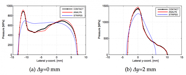
Regarding the normal problem, when the contact patch is not elliptic due to the geometry of the bodies, the settled methods are not able to correctly capture the peaks in the normal stresses, or the contact area with low stresses can be unwillingly disregarded. In3 this is solved by accounting for the surface deformations in a simplified way, instead of neglecting them. From a practical point of view, it means that the virtual surface that represents the contact area is not necessarily normal to the undeformed contact plane, which was not accounted for in previous models. The result is impressive, as it can be seen in the figure.

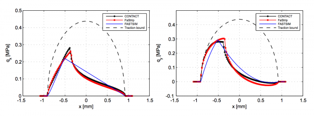
When modelling the tangential contact, things start to get a little more complicated, as there is no analytical solution to the problem that could be used as a start point. The most commonly used algorithm to compute the tangential stresses and the stick and slip areas inside the contact patch is FASTSIM, developed in the late 1980s as a fast way of calculating it for the not-so-powerful computers at that time. But even if it is not precise enough (errors in the magnitudes can be up to 30%) the method accounts for the direction of the local stresses inside the contact patch very efficiently, allowing the computation of non-dismissible spin values in the contact patch. The new calculation method in 4 combines the computation of these sliding directions –and only the directions– with the Strip theory of contact between bodies. This algorithm is compared to previous methods, specifically the result in creep force estimation for different creepages and spin value combinations, on one hand, and stress distribution along the rolling direction on the other hand. Once again, its precision is astounding.

The combination of these two novel methods for the calculation of the variables in the contact patch is still slower than the simplest methods used nowadays, in the order of 10 milliseconds per contact patch calculation. However, the precision reached regarding contact area, stress distribution, and sliding speed distribution is amazing compared to these fastest models. It is definitely worth its implementation for vehicle dynamics analyses.
There might be a drawback, though. Although the excellence of this work is undeniable, the gain by its practical application in multibody simulation software might not be as big. For instance, the influence of very small variations (fractions of millimetres) in the profile geometry around the contact patch might have a huge influence on the peak stresses experienced in the contact area. But as the profile is not continuously updated but in discrete steps, the information that is lost in this discretization can have more influence than the actual benefit of more precise contact models. We will have to wait for its practical implementation to see the applied results.
References
- M. S. Sichani, R. Enblom, and M. Berg (2014) “Comparison of non-elliptic contact models: Towards fast and accurate modelling of wheel–rail contact,” Wear, vol. 314, no. 1–2, pp. 111–117 ↩
- N. Burgelman, M. S. Sichani, R. Enblom, M. Berg, Z. Li, and R. Dollevoet (2015) “Influence of wheel–rail contact modelling on vehicle dynamic simulation,” Veh. Syst. Dyn., vol. 53, no. 8, pp. 1190–1203 ↩
- M. S. Sichani, R. Enblom, and M. Berg (2014) “A novel method to model wheel–rail normal contact in vehicle dynamics simulation,” Veh. Syst. Dyn., vol. 52, no. 12, pp. 1752–1764 ↩
- M. S. Sichani, R. Enblom, and M. Berg (2016) “An alternative to FASTSIM for tangential solution of the wheel–rail contact,” Vehicle System Dynamics DOI: 10.1080/00423114.2016.1156135 ↩
5 comments
Great article! I imagined there had to be a way to know when to change train wheels. Yet, in practical terms, does it really matter that you know whether it takes 1 of 10ms to know that there is a problem in the wheels?
This would not calculate the exact time where the damage occurs, but would allow to predict much better the damage modes that occur in the wheelset along its operational life. Or at least, it would give the best input possible to the models that do calculate the damage!
The problem of the time it takes to calculate one simulation step is crucial when looking at the whole picture, as train dynamics are simulated for several seconds (one minute is a good reference) and a 15s calculation of the contact patch for every millisecond means 15 000 times more calculation time than simulation time (1 min simulation of a train running on a curve would take more than 10 days to calculate, and that only accounts for the contact patch calculation and nothing else). Here is where an accurate model with substantially less processing time becomes useful.
And thanks for the comment! 🙂
Oh, I think I got the point – you guys are finding ways to speed up simulations, among other things. Thanks again for your response. Regards
[…] El que los trenes consuman tan poca energía se debe a la poca fricción entre las ruedas y los raíles. Entender esta interacción es fundamental para optimizarlos. Carlos Casanueva en The sweet spot of wheel-rail contact modelling […]