Stable independently rotating wheels? Just turn them inside out

Classic rail vehicles have rigid wheelsets: both wheels are interlocked and have the same degrees of freedom (DoF), so they share all their displacements. They also have positive conicity, this is, the wheel surface on the contact patch is conical and, if we extend these ideal cones, their base would meet at the centre of the wheelset. This bi-conical geometry is statically stable and allows wheel negotiation, enabling the whole vehicle to be stable and safe up to certain speeds.
This geometry has its drawbacks too. Both wheels share rotating speed, so when the wheelset moves laterally and generates a rolling radius difference between the wheels, their longitudinal speeds will be slightly different to the linear speed of the whole vehicle, generating a sliding in the contact patch that will wear out the material on wheels and rails. Also, when negotiating very tight curves, the rolling radius difference is not enough for a smooth rolling, so the outer wheel in the curve is forced into flange contact, where high contact forces and huge sliding speeds occur at the contact patch, generating extremely high wear, high-pitch squealing noise and greater energy consumption. The angle between the wheelset and the curve radius is named “angle of attack”, and is a quite important parameter for the study of curve negotiation, as it states how well the suspension system adapts to the curve.
Since their first appearance, the requirement of the wheelsets have evolved significantly in two directions: first, high speed trains with speeds over 300km/h which need to be stable at high speeds; and second, Light Rail Vehicles (LRV) which need to negotiate tight curves smoothly. When designing a classic vehicle with rigid wheelsets, vehicle suspension is optimized for both high speed stability and curve negotiation. These have contradictory requirements, so an optimization trade-off must be applied, depending on the most valuable behaviour of these two for the designed vehicle.
For LRVs there is an additional option for the improvement of its curving behaviour, i.e. the use of independently rotating wheels. In this configuration, the wheels share all the DoF except for the wheel rotation, which is uncoupled. This way, in extremely tight curves both wheels can roll at different speeds, avoiding all the previously stated problems. However, this configuration has a major drawback: it is statically unstable. The short explanation would be that the left wheel can rotate forward and the right wheel backward, generating an unconstrained yaw displacement. In rail vehicle jargon, independently rotating wheels have no self-steering ability.
There are a few alternatives for solving this static instability. The obvious one is using extra linkages to restrict the yaw displacement of the wheelset, but needs couplings which affect bogie or even carbody. There is a particularly ingenious system that uses gravity stiffness to self-centre the wheelset 1, called the Einel-rad-Einelfahrwerk (EEF) bogie, but it is not widely used because of the complex geometry of the bogie. In order to achieve self-steering with a conventional wheelset and bogie structure, recently Suda et al. proposed to invert the conicity of the wheelsets, i.e. to incline the surface contrary to conventional wheelsets or simply flip the wheels inside-out 2.
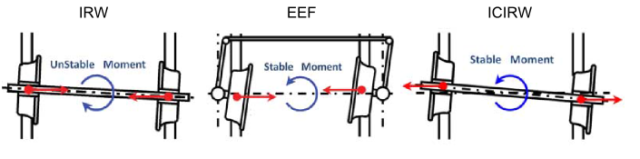
There is a good reason not to do this in a conventional wheelset: it is statically stable, but dynamically unstable. Yet, when using it in independent wheels, the extra rotation capability kills this dynamic instability and makes the system both statically and dynamically stable. So, on paper, a wheelset with independently rotating and inverse-conicity wheels is mathematically stable. They simulated it in a Rail Vehicle MBS software with realistic wheel profiles and the simulations confirmed their mathematical results.
The authors went one step further and built small 1/10 scale prototypes. When physically constructing the inverse-conicity wheels, the flange can be placed in the inner part, generating a U shaped profile; or it can be placed in the outer part, just flipping the whole wheel profile; so they built both in order to compare their behaviour. The experimental setup consisted on a tangent track followed by tight curve, with a downwards slope of 13%. Results were compared to previous studies of conventional wheelsets, and concluded that i) inverse-conicity IRW allow smaller angle of attack in the curve, thus reducing wear and energy consumption, and ii) outer flange produces a smaller angle of attack than inner flange profiles, and the speed gain during the curve is bigger, meaning it has less resistance to the longitudinal displacement.
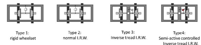
In order to complete their study, full scale simulations were carried out for three different wheelsets, with a LRV running on an international gauge track. Being a full model and not only a bogie, it includes yaw dampers between bogie and carbody, which dampen the yaw vibrations but also deteriorate slightly the curving behaviour. But then, IRW are meant for extremely tight curves where the vehicle speed is very low. For low speeds the influence of the dampers is much lower, so its effect will be negligible. The preliminary simulations showed excessive lateral forces even for the IRW vehicle, so they included a forth case with semi-active yaw damper in order to control them (Figure 2).
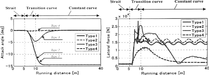
The simulation results are depicted in Figure 3, where it can be noticed the substantial gain when using IRW with inverse tread conicity. First of all, the wheelset goes back to the radial position during the circular curve, so longitudinal contact forces will be reduced up to virtually disappearing. Also, for the controlled semi-active damper case lateral contact forces are dramatically reduced, which will avoid derailments and increase the life of the wheelsets.
The inverse-conicity IRW with outer flange model seems very promising except for one detail: outer flanges mean that the whole track system must be redesigned, specially switches and crossings, and that is not going to happen any time soon. This is also a dynamic analysis, so problems might arise when studying other characteristics such as comfort. Anyway, it is good to have researches who try to improve the rail vehicle topics that are written in stone. Maybe someday we will all travel in city trams with inverse-conicity wheels.
References
- F. Frederich, Dynamics of a bogie with independent wheels, Vehicle System Dynamics: International Journal of Vehicle Mechanics and Mobility, Suppl. 19 (1989), pp. 271–232. ↩
- Suda Y., Wang W., Nishina M., Lin S. & Michitsuji Y. (2012). Self-steering ability of the proposed new concept of independently rotating wheels using inverse tread conicity, Vehicle System Dynamics, 50 (sup1) 291-302. DOI: 10.1080/00423114.2012.672749 ↩
1 comment
[…] Para complicarlo un poco en el párrafo final, aclarar que todo esto es cierto siempre que las ruedas y el eje estén rígidamente unidos. Y es que investigadores japoneses han demostrado que, desacoplando el ángulo de rodadura de las […]