A new type of arthropod-inspired cameras
A new type of arthropod-inspired cameras

In our eyes, the cornea and crystalline lens project an image of the world onto the retina. There, this image is sampled by the rods and the cones —the light-sensitive cells of the vertebrate eye—, coded as a sequence of electrical signals and preprocessed by other neurons before being sent to the brain via the optic nerve. This pattern is roughly the same as the one followed by a video-camera, and sometimes it is easy to forget that there are other ways of imaging the world. However, this is very far from being true, as evolution has shown us by producing a great number of different eyes.
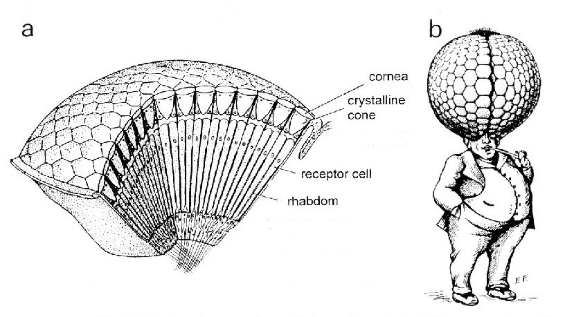
One of the most successful designs, considering the sheer number of species and individuals that make use of them are apposition compound eyes (fig 1a). An apposition compound eye is composed of many independent one-pixel detectors, the ommatidia, each one looking at a different direction. Each ommatidium has its own little lens that focuses light from a small region of the world onto a single photoreceptor. The number of ommatidia varies largely across species. Some dragonflies, visually guided and rapidly flying predators, have huge compound eyes with 20.000 ommatidia or more each. Each honeybee compound eye has around 5.000 ommatidia, while the smaller single eye of the waterflea Daphnia has only 22 ommatidia.
However, apposition compound eyes seem far from being a good imaging option. As noted by Henry Mallock in the late 19th century, compound eyes have bad resolution, because their small lenses diffract strongly the incoming light. If we want to double the resolving power of a simple eye, we just have to double its size, so the lens is now two times bigger. With compound eyes, this trick simply does not work. Resolution is both limited by lens diffraction and the number of ommatidia: we have to double both to double the resolution, and this implies multiplying by four the total size of the eye! If we were to have compound eyes of the resolution of our simple eyes, they would have 1 m in diameter, and that would give us the weird look captured by Kirschfield in his figures (fig. 1b).
Compound eyes have, of course, some advantages. That camera in your phone makes poor pictures, but it can keep in focus simultaneously all parts of the image. The same happens with the tiny lenses of the compound eye, which can focus simultaneously from very close to the eye to infinity. The small focal length and the need to worry only about a single photoreceptor per lens also reduces the effect of off-axis aberrations. Finally, compound eyes provide some insects with a full panoramic view without big distortions, while allowing for different light adaptation in different directions.
Do these advantages overcome the drawbacks? Or are users of compound eyes unknowingly trapped in an evolutionary cul de sac? Experts in the field don’t seem to agree. However, the controversy does not discourage some groups of engineers that design and build artificial versions of compound eyes. The final goal is to adapt them for giving panoramic view to little flying robots, as an alternative to cameras with heavy and aberration-prone fisheye optics.
In a recent letter in Nature 1, John A. Rogers, from the University of Illinois, and his colleagues in the USA and China have presented an artificial compound eye with 180 lenses. The main difference of this prototype from previous ones is the much simplified manufacturing process. The whole eye is built in a plane elastic material, and then stretched to form a convex eye.

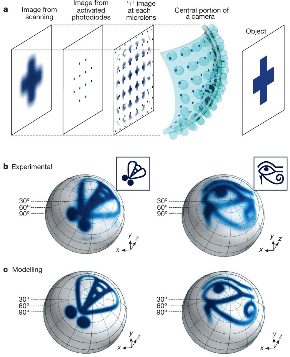
The optics are formed by a plane piece of PDMS elastic polymer with an array of 16×16 convex micro-lenses (fig 2), created by the use of a micro-machined aluminium mould. A second layer is a matching array of silicon photodiodes, each of them placed in the focal point of the micro-lenses, and interconnected via traces of metal (chrome and gold). Each of the 180 lens and photodiode pairs thus formed is the artificial equivalent of an ommatidium. The sheet was then stretched into hemispherical shape without a measurable change in the optical parameters of the micro-lenses. A black support and a black perforated cover are used as screening pigment, reducing the negative effect of internal reflections and stray light.
These apposition compound cameras have good yields and characteristics. They have a field of view of 180º, with a similar number of ommatidia to some species of ants or beetles. This reduced number allows only poor resolution, but simple forms can be recognised (fig 3). A particular advantage of this design is the possibility of tuning dynamically the curvature of the eye to improve resolution in certain directions.
Only time will tell if these designs can be improved to be more useful than simple cameras with fish eye lenses in certain situations, and whether they are the first steps towards a world of tiny robots using compound eyes for navigation.
References
- Young Min Song et al. Nature 497, 95–99 (2013) doi:10.1038/nature12083 ↩