ITER: Engineering challenges of putting the sun into a box (Part 2)
ITER: Engineering challenges of putting the sun into a box (Part 2)
In this second part of the series about ITER (see first here), we start giving a more detailed description of the ITER machine. Then, we address some important challenges that have been identified for each of its parts and scientists’ plans to solve them.
Tokamak design
After all, the core of a nuclear plant is a very complex machine for heating water. Once we have water steam, the parts in charge of producing electricity are not much different than in many other electric plants.
The heart of the ITER machine is the chamber, or vessel, where nuclear fusion occurs. Among a few possibilities, ITER decided to follow the design named Tokamak, a Russian acronym for “toroidal chamber with magnetic coils“.
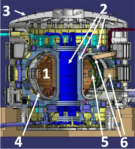
The most relevant parts of the machine have been numbered on the picture above:
- The Vacuum Vessel (VV): this empty, toroidal chamber is where plasma is confined.
- Magnets: Superconducting electromagnets provide the magnetic fields required to keep the plasma rotating inside the vessel without touching its inner walls. An extra set of magnets (not visible in the figure) had to be added to the design in a posterior stage to stabilize the plasma, as we will see later.
- Cryostat: The tokamak will be enclosed in a cryostat that isolates the inner hot parts from the superconducting magnets, which are cryogenically cooled.
- The so-called “first wall“: this is the part of the chamber that will be more closely exposed to the hot plasma and to the strong flux of hot neutrons.
- Heaters: They provide the energy required to start nuclear fusion in the plasma.
- Monitoring sensors: Mechanical stress, temperature, vibrations, etc. are to be closely watched during operation.
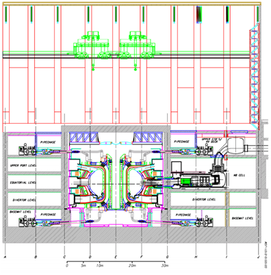
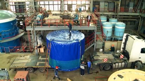
An entire building is devoted to containing the vessel, which spans over four stories as shown in this cross section view:
Magnetic fields: design and generation
Nuclear fusion occurs at the plasma, whose purity must be assured in order to achieve self-sustained reaction. This implies keeping it away from the surrounding walls of the vessel in a well-defined volume in space. In other words: it must be kept floating around in the middle of the chamber. That is the so-called confinement problem.
Confining a material which is at millions of degrees of temperature is not a minor issue. As the reader surely knows, temperature is a measure of the average kinetic energy of each particle. Thus, extremely hot plasmas imply particles moving at random directions at huge velocities.
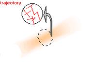
Somehow, a tokamak must correct the trajectories of all those particles to avoid them to collide with the vessel. Since plasmas are made up of charged particles (nucleuses and electrons) an evident way to deflect their trajectories is using magnetic fields. So, a linear magnetic field would be enough to force particles to describe circles around the field lines, as shown in the figure:
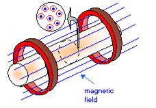
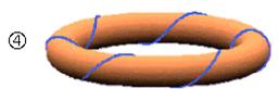
To keep particles confined in a small volume we can take a long rectilinear magnet and blend it to form a toroidal magnetic field, which is one of the two main fields that will operate in ITER. Basically, it is generated by a set of circular magnets surrounding the torus.
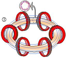
Practice, however, has taught nuclear physicists that this field on its own is not enough to keep losses as low as desired. Ideally, field lines should be helicoidal around the torus, which is achieved by means of an additional set of magnets producing a field perpendicular to the toroidal one. This poloidal field is not generated by any external magnet: instead,a strong current (15 millions Amperes) is induced into the hot plasma in the torus longitudinal direction. After all, plasma behaves as an electrical conductor due to the free electrons that float around.
According to the design plans 1, 80,000 km of superconducting cables (Nb3Sn) are required to wire up the 18 toroidal magnets, the central solenoid in charge of inducing the current into the plasma and a number of other auxiliary magnets to fine tuning the magnetic field. In comparison, the LHC at CERN has “toy magnets”, with “only” 7,600 km of superconductors!
With an overall of 48 magnets, the generation of the magnetic fields of up to 11.8 Teslas (200,000 times the Earth field) represents the biggest part of the machine, accounting for 6540 tons. From the mechanical point of view, the toroidal field magnets are particularly challenging due to the mechanical stress conditions they must face: the interaction of these magnets with the fields generated by the plasma current and other magnets will lead to strong pulsed toroidal forces, which obviously suggests that fatigue may degrade the magnet structure over time. In order to resist to these induced forces, rings of glass fibres are to surround each magnet with an inward radial force equivalent to the pressure of 6,000 tons.
The vessel walls
Although only tiny amounts of Deuterium and Tritrium, about 0.5 grams, form the mix that will fuel nuclear fusion in the plasma inside the Tokamak, huge amounts of heat are generated in the reaction, with 80% of the energy escaping the plasma as hot (fast) neutrons. Since neutrons have no electric charge there is no magnet capable of directing them to some predefined location, which becomes a headache for nuclear engineers: the entire first wall of the toroidal vessel will suffer an intense bombing of hot neutrons.
Thus, plasma-facing components must meet two design criteria: (i) be rough enough to resist the radiation during long periods of time (months to years), and (ii) also be able to evacuate heat. It is that heat, recovered via water refrigerating circuits, what ultimately generates the electric power. Just for comparison, the Sun surface emits 70 MW/m2, while state of the art tokamaks present only seven times less power density (10 MW/m2) 2.
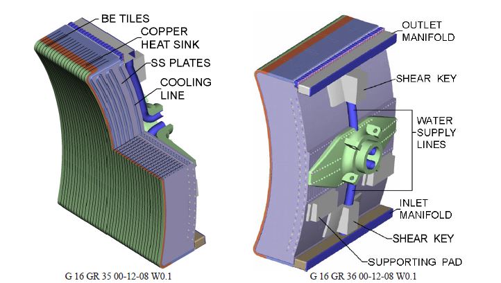
In ITER, the first wall material has been selected to be a 1cm thick layer of Beryllium, for its optimal properties in resisting becoming radioactive when facing the neutron flux. Behind that, another 1cm layer of copper will redistribute the heat load as uniformly as possible, for the third layer of solid steel (30cm) to transfer the heat to circulating water. In order to make the wall modular and maintainable, it will be divided into 421 modules, each with 1 ton of steel.
Handling dangerous ELMs
As we saw, controlling the plasma inside a Tokamak requires strong and carefully engineered magnetic fields. Even with those fields, part of the plasma escapes; so, you can imagine how much scientists struggle to keep it as located in space as possible. Luckily, there is something called “high confinement” mode (H-mode). It was discovered by pure chance, without nobody expecting it. During an experiment in 1982 at the Max Planck Institute for Plasma Physics, Fritz Wagner observed a sudden change in the behavior of plasma as it was heated inside a Tokamak: at some point, the plasma losses abruptly dropped and turbulences at the plasma edges practically disappeared. He just discovered the transition from L-mode (low confinement ) to H-mode, probably the most relevant single advancement in the history of fusion reactors. Even nowadays, physicists do not fully understand yet the mechanisms that allow this sort of “phase change”, so performing numerical simulation of this behavior is still in the limits of the state-of-the-art.
As usual in Nature, there was a price to pay for a more stable way of confining plasma: a new type of quasiperiodic instability appeared. Just like the Sun has solar flares, sometimes the H-mode plasma abruptly has “storms” amid the calm.
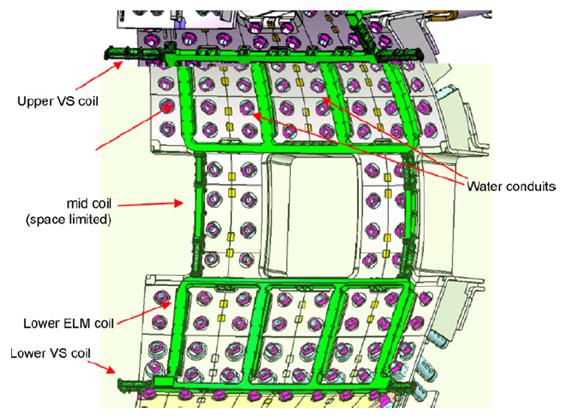
They are named ELM (Edge Localized Mode), and are instabilities at the plasma frontiers. With each ELM, the surface of the vessel must face a sudden increase of the temperature of thousands of degrees. Scientists expect to see thousands of ELMs at ITER, and it was found 3 that ELMs are more damaging than originally though. To cope with this potentially dangerous effect, ITER design was changed to include additional coils that will attempt to control ELMs.
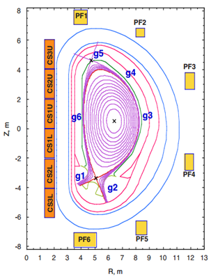
ELMs have been a headache for the all the agencies involved in ITER design: the new electromagnetic coils will be very close to the inner wall, thus must robustly resists large thermal expansions due to the high temperatures, while ensuring a 20-years reliability. On the bright side, extra coils will provide more degrees of freedom in the design of the vertical magnetic fields. The final ITER design now includes the new ELM coils shown in the figure below.
Apart from those coils, nuclear engineers found another way to calm down ELM instabilities. The “snowball in hell” technique consists of throwing a small pellet of cold fuel directly into the plasma. Rude as it may look, it produces a minor instability which, somehow, prevents the much larger ELMs.
In the words of the scientists, it may be seen as a way of “burping the baby” to prevent greater risks. Alberto Loarte Prieto, a Spanish physicist now working in Germany, gives more details on ELMs in the following video.
References
- International Atomic Energy Agency. “ITER Technical basis”, Vienna, 2002. ↩
- The TORE Supra Tokamak website. CEA, 2006. ↩
- Ioki, K., A. Bayon, C. H. Choi, E. Daly, S. Dani, J. Davis, B. Giraud et al. “Progress of ITER vacuum vessel.” Fusion Engineering and Design (2013) ↩
2 comments
[…] this third and last part of the series (1, 2) about ITER we continue giving insights into the most outstanding aspects of the ITER machine […]
[…] de los artículos publicados en MappingIgnorance.org: 2 y […]