ITER: Engineering challenges of putting the sun into a box (Part 3)
ITER: Engineering challenges of putting the sun into a box (Part 3)
In this third and last part of the series (1, 2) about ITER we continue giving insights into the most outstanding aspects of the ITER machine design.
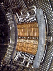
Divertor
The ITER divertor is a part of the vessel, placed at the very bottom, whose twofold purpose is (i) helping in shaping the plasma and (ii) getting the “trash” out while plasma is sustaining the fusion reaction.
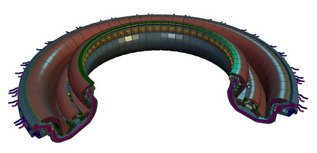
Comprising 54 identical blocks, or “cassettes”, the shape of the divertor is engineered such that its surfaces will be hit by energetic particles that escape the plasma. By placing these “sinks” at the bottom of the vessel, far from the core plasma, the interaction with the fuel is minimized, hence reducing the risk of introducing impurities. Actually, the divertor is also in charge of recollecting helium ash, a byproduct of the fusion reactor which must be evacuated to maintain the highly-pure composition of the plasma.
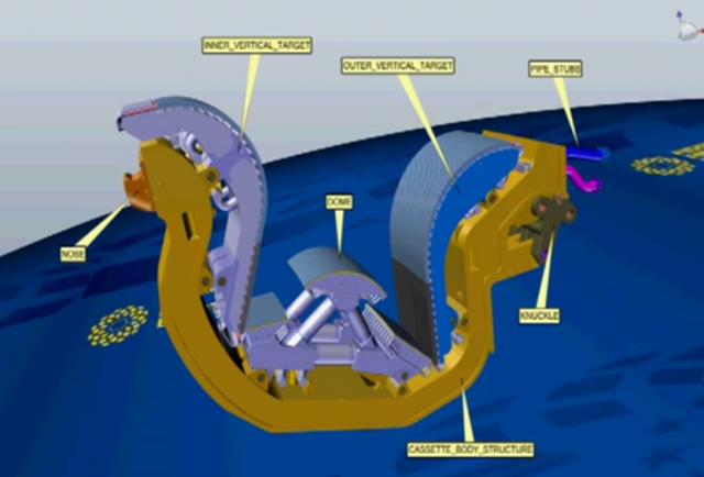
Magnetic confinement is used to keep the plasma far from the main walls of the chamber, but there are still three parts which have the highest exposure to plasma: the inner and outer vertical targets and the dome of the divertor (see figure above). Choosing its material is therefore one of the most stringent problems of fusion reactors, and much experimental work is still required before scientists find the optimal material for commercial usage. The material must exhibit good thermal conductivity to efficiently evacuate heat (it will be exposed to 3000ºC), but simultaneously it cannot become too radioactive (it is expected to be in operation for 20 years inside a fusion reactor). Two options were considered for ITER: carbon fibre reinforced carbon (CFC) and tungsten, although financial cuts will probably allow experimenting with only one of the materials (tungsten).
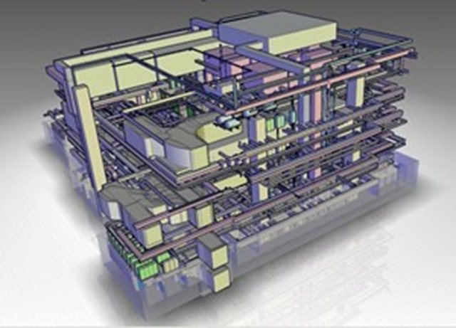
Repairing divertor cassettes is expected to be a common operation during ITER operation. Since many of those parts may be “activated” (radioactive), a separate building has been designed and built exclusively for security reasons: it is called the “hot cell“.
Heating the plasma
We saw earlier that temperatures in excess of 100 million degrees must be reached before nuclear fusion starts happening inside the plasma. How can we heat a gas cloud to such an outstanding temperature?
Firstly, the same magnetic fields that help the plasma to stay confined will also induce a current into it. And just as in any electric heater, a current flowing through an imperfect conductor sees an Ohmic resistence, which dissipates energy in the form of heat. In spite of the huge currents to be induced in the plasma (millions of Amperes), this effect will only heat the plasma up to 10 millions of degrees.
The additional heating until the hundreds of millions of degrees can be achieved by two mechanisms: injection of accelerated ions (where the collisions of the high-energy particle with the plasma redistribute the temperature pump), and radio heating. Basically, the latter consists of turning the Tokamak into a huge microwave oven like those on our countertops. Dozens of RF antennas will create an electromagnetic field inside the vessel that will help “shaking” the plasma particles, heating them up.
Ultra-High Vacuum
Managing the Ultra-High Vacuum design constraint is another big headache for ITER engineers. The experiment specifications include that the plasma chamber must be kept in Ultra-High Vacuum (UHV), roughly in the range of 10-5 to 10-7 Pa. From the engineering point of view, working with a UHV container means discarding all common materials and practices: plastics, glues, standard welding, etc. all tend to free tiny amounts of gasses if exposed to UHV, hence their total prohibition in the ITER chamber.
Mechanical design must also account for UHV. Moving and rolling parts in ITER cannot be lubricated with common oil because it would contaminate the vacuum. Expensive replacements exist, like molybdenum disulphide (MoS2), which tolerate well the vacuum. Metal actuators and mechanisms can also emit contaminants due to oxidation, even if made of steel. That is why every metallic part that has to operate inside the chamber will go through a baking process to assure that any tiny gas pocket that remains from imperfections in the assembly are eliminated.
Redesigned in 2012 1, the primary role of the Vacuum Vessel is to provide a first barrier against accidental losses, while being able to recover all the excess heat that will ultimately become the net energy gain. UHV is assured during the construction of the vessel modules by using Electron beam(EB) welding for almost all joints.
Robotic systems
Most of the ITER instruments will be placed out of the vessel. However, some electronics are unavoidable in subsystems that eventually will be exposed to the environment inside the vessel. An example is the robotic manipulator (a “robot arm”) that will be in charge of inspecting the inside walls of the tokamak between two plasma shots. Even when no plasma is to be contained, the superconductor magnets cannot be switch off so easily: the thermal and tensile stress generated in the magnets with each run cycle limit the number of times they can be switched on and off during the expected life of ITER.
This means that the robot arm will have to operate in an extremely hostile environment: high radiation levels, high temperatures and strong magnetic fields. None of them are good friends of machines and electronics. In the particular case of electronic devices, the ITER Radiation Hardness Manual 2 recommends only using a few components that are known to be rated for radiation levels as high as 10MGy.
Naturally, designers can forget all the advances in electronics we have witnessed since the 1960s: only a few discrete transistors can be employed, with integrated circuits being forbidden for their sensitivity to radiation. If something as simple as a JK logic flip-flop is required… it will have to be built from discrete transistors!! So we can expect that most of the robot arm electronics will be well hidden behind the first wall, with only the most rudimentary actuators and sensors placed in the arm body itself.
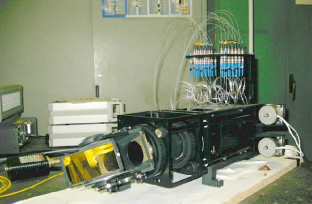
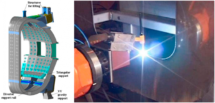
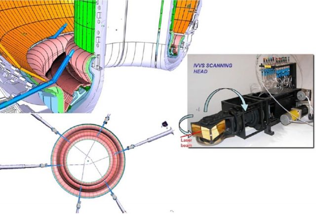
The ITER laser in vessel viewing and ranging system (IVVS) is a prototype of a robotic arm to be used inside the vacuum vessel for visual inspection, designed by the Italian Fusion Association ENEA 3. Range measurements are provided with an optical laser, whose source would be behind the vessel walls, and which will be guided to the end of the arm through optical fibers, hardened to support the radiation levels. Scanning the vessel with one single laser beam is possible by rotating a prism that redirects the beam. This simple movement, however, cannot be done with ordinary motors (remember that it will work under an intense external magnetic field), but with piezoelectric motors. Some parts of the arm has been designed in stainless steel and others in titanium alloy to reduce the eddy current drag caused by the poloidal field. Eddy current drag are actually unavoidable and can even produce vibrations which cannot be easily damped by long robotic arms. One solution is to deliberatively employ good conductors to minimize those forces.
One final curiosity about the usage of the robotic arm inside ITER is that the localization of the robot inside the chamber, something required to correctly interpret its readings, is expected to have an easy solution: since the magnetic field inside the machine is known with a high accuracy (in the order of one part per million), measuring the local field at different points of the robot permits computing its absolute radial position. Using one 3D Hall sensors per segment will allow knowing the exact 6D absolute position of the arm. Accuracies in the order of 0.8 mm are expected. At least, there is one problem with an “easy” solution in the gigantic ITER puzzle!
Sources:
[1] Loarte, A. (2008, October). Power and particle fluxes at the plasma edge of ITER: Specifications and Physics Basis. In Proc. 22nd Int. Conf. on Fusion Energy 2008 (Geneva, Switzerland, 2008).
[2] Holtkamp, N. (2009). The status of the ITER design. Fusion Engineering and Design, 84(2), 98-105.
[5] Cordier, J. J., Hertout, P., Gargiulo, L., Cantone, V., & Soler, B. (1998). New magnetic measurement of the Tore Supra toroidal field profile. In SOFT: Symposium on fusion technology.
References
- Ioki, K., Choi, C. H., Daly, E., Dani, S., Davis, J., Giraud, B., … & Wu, S. (2012). ITER vacuum vessel design and construction. Fusion Engineering and Design, 87(5), 828-835. ↩
- J. Campbell, Radiation hardness manual (RAD), Volume II: Gamma irradiation, Ref.ITER_D_222RR8, v1.0, ITER Organization, 2007 ↩
- Jean-Baptiste Izard (2013). Development of Remote Handling Technologies Tolerantto Operation Ready Fusion Reactor Conditions. PhD thesis, Tampere University of Technology ↩
1 comment
[…] (Traducción de los artículos publicados en MappingIgnorance.org: 2 y 3) […]